Designer
The “Designer” section allows the 3D modelling of the system, the flow calculation and the hole sizing.
At the centre of the section is a CAD environment for the drawing of the structure of the aspirating system with all its components.
On the sides of the section are two panels with the tools for the system project design. The left panel contains the building plans and the right panel the modeling tools.
These panels can be expanded or collapsed by means of the appropriate arrows.
The designer, using the various tools available on the side panels, can draw the system, also by importing a project from a drawing file external to the software (CAD floor plans in DWG, DXF or PDF format), and by inserting the various components it must comprise.
At any time it is possible to check the validity or the correspondence to the chosen detection classes (refer to “Detection Classes”), by means of the flow rate calculation tool supplied.
There is also a section-specific menu bar with the following buttons:
-
 ,
,  , buttons to cancel or repeat the last operation in the memory, limited to each floor
 -
 , button that automatically generates a system report and the calculation of the flow rates in DOC format
 -
 , button that generates a JPG file, captures screenshots of the designer’s current video screen
The captured screenshots are saved in a folder, accessible via the
 button and are automatically inserted into the report document.
System layout limitations
During the drawing phase the software will, by default, have already set the parameters required or restricted by legislation.
In this way certain operations, such as failure to respect the minimum distances between objects are prohibited by the software, preventing the user from drawing or inserting elements in prohibited points.
For other types of operations that may fail to comply with the regulations, the FA/STUDIO has a flow rate calculation engine that warns of non-conformities or design defects.
|
System layout limitations |
operation denied by the designer |
flow rate calculation notice |
|---|---|---|
|
overall length ≤ 160 m |
|
|
|
distance of a sample hole from the FA100 device ≤ 100 m |
|
|
|
distance of a hole from the next element ≤ 25 cm |
|
|
|
distance between holes ≤ 10cm |
|
|
|
exhaust pipe length ≤ 10 m |
|
|
|
distance of a sampling capillary kit from the next element ≤ 25 cm |
|
|
|
distance of a T-fitting from the next element ≤ 25 cm |
|
|
|
only one dust filter for each detector module |
|
|
|
distance of a dust filter from the FA100 device ≤ 2 m |
|
|
|
only one condensate trap per detector module |
|
|
|
distance of a condensate trap from the FA100 device ≤ 2 m |
|
|
|
no holes between the FA100 device and the dust filter |
|
|
|
no holes between the FA100 device and the condensate trap |
|
|
|
number of holes based on detection class |
|
|
Navigation
In the upper part of the drawing section are the navigation tools common to the main CAD modeling software:
-
 , allows top view of the drawing in its entirety
 -
 , allows enlargement of a point in the drawing
 -
 , zoom of the selected area
 -
 , allows moving closer to or further away from the work plane (“Shift” + right mouse button)
 -
 , to move on the work plane (“Ctrl” + right mouse button or directional arrows)
 -
 , to rotate the view (“Alt” + right mouse button)
 -
 , as per the
  button without rotating the view
Once a navigation tool has been selected, to cancel or return to “normal” mode simply press the right mouse button or the “Esc” key on the keyboard.
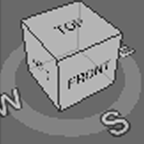
Through the cube on the top left it is possible to rotate the view by clicking on an edge and dragging. By clicking on each face of this it is possible to have its default view.
Drawing operations are carried out on the work plane that coincides with the current view.
Project floor plans
For each project there is the possibility of structuring the system on multiple floors, and for each of them it is possible to apply a different floor plan.
To add a floor it is necessary to open the left side panel and move the mouse over the roof of the “house”. After doing so the “Add” button will appear.
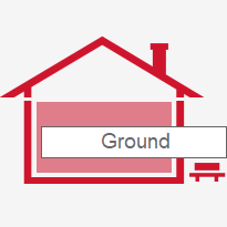

It will be possible to change the label of the floors or their position (by means of the directional arrows)
To delete a floor, simply click on the relevant  button. This will also remove all the aspirating devices inserted on the floor in question as well as the associated floor plan.
Plans
Via the right side panel, under “Floor plan”, can be found three buttons that allow operations to import, export or delete a floor plan from the work plane.

Clicking on “Load” opens a window that allows the selection of a file in one of the 3 accepted formats (DWG, DXF, PDF). If a file in CAD format (dwg, dxf) is added, it will be necessary to specify the unit of measurement with which the Autocad file was created (metres, centimetres, millimetres). For pdf files it will be necessary to specify the floor plan scale.
The base work plane is the plane of the cube defined as “Top”. The two-dimensional drawings will therefore be positioned on this plane.

By means of the “Export” button it is possible to export in a CAD format the entire project (floor plan with the piping drawing). Only visible elements will be exported, as selected in the “Layer” panel.

Using the “Delete” button will only delete the floor plan and not the system that has been modelled. If it is necessary to hide the floor plan temporarily, it is sufficient to deactivate the “Floor plan” option found in the “Layer” section.
Viewing and layer
Through the right side panel “Layer” it is possible to set the display mode of the drawing area and the contained elements.
The following options allow both the display of the relevant element and the creation of a customized layer when exporting the project into a CAD format:
-
Holes, option that highlights sampling holes
-
Index, Label, Diameter, options that display via caption the numerical index on the piping, the description and the diameter of the hole
-
Coverage, option that highlights the hole coverage area on the base plane
-
Length, option that displays via caption the length of the branch of piping between two adjacent elements
-
Floor plan, option that displays the drawing imported into the project
The following options affect display mode only:
-
Grid, option that displays a grid on the base plane
-
Prospective, option that simulates a perspective depth in the case of a three-dimensional view
-
Wireframe, option that replaces 3D elements with linear graphic elements
-
Orto mode, if selected, allows to draw horizontal pipes only in four directions, taking automatically into account the 90 degree curves, that will be added to the bill of material.
If deselected, it allows you to draw pipes in any direction without considering the 90-degree bends. In this case, it is assumed that the installer uses a flexible pipe, which will not be automatically added to the bill of materials.
However, it is possible to combine both modes in the same project, inserting sections in orthogonal mode and sections in free mode.
-
Curve, option which, during the piping drawing phase, automatically inserts 3D curves, with any appropriate corrections
The modification of this option applies to curves drawn from that point onwards and not to those already positioned
-
Text size, bar for selecting the size of the writing displayed
FA100 Insertion
To add a FA100 device it is necessary to:
-
Open the right side panel.
-
Select the “Device” element on the “Add” panel.

-
See box bottom right.
Via the numeric keyboard, specify in cm the desired installation height of the device (default “0”).
-
Click on the point where the device is to be inserted or press the “Enter” button.
To cancel, press the “Esc” button or right mouse click on the text.
Clicking with the right mouse button on the device figure opens a contextual menu where it is possible to:
-
associate the device with a real device that requires configuring
-
rotate the device on the horizontal plane (if no pipes are connected)
-
reorder the numerical index of the holes
-
move the aspirating device along with the entire connected system
-
delete the device and the entire connected system (if a device associated with a module configured in the solution is deleted, it will be disassociated automatically)
-
hide the selected device
-
hide all unselected devices and pipes
-
make all previously hidden elements visible.
This option is always accessible even by clicking on any empty point in the designer window.
-
display the information panel
Modelling the piping
Through the right side panel under “Add” option, it is possible to select the “Pipe” button. At the same time, yellow arrows appear on the work plane at the points where pipes can be added.

If a new FA100 has been added there will be two main couplings “D1” and “D2”, relating to the two FAD100 internal detector modules and the exhaust pipe.
By clicking on a vertical arrow it is possible to move up or down in order to insert piping, whereas the horizontal arrow moves in all 4 directions on the plane. By right clicking on the mouse the piping interrupts.
Via the numeric keyboard, it is possible to enter the length of the pipe expressed in cm (see the box at the bottom right).
To shorten the inserted pipe, click in the direction opposite to the pipe or enter a negative value via the numeric keyboard.
To lengthen a pipe beyond the size of the screen, it is possible also to select the pipe and move around using the directional arrows on the screen and on the keypad.
Through the contextual menu (via the right mouse button), it is possible to:
-
indicate the length of the pipe, in cm
-
reverse the position of the two detectors associated with the selected pipe
Warning
This operation invalidates the flow calculations already done, therefore, it will be necessary to redo the calculations in order to guarantee the correctness of the simulations.
It is recommended to warn the user via a message or notification at the time of use.
-
delete the device and the entire connected system (if a device associated with a module configured in the solution is deleted, it will be disassociated automatically)
-
hide the selected pipe
-
hide all devices and other unselected pipes
-
make all previously hidden elements visible.
This option is always accessible even by clicking on any empty point in the designer window.
-
display the information panel
In the drawing phase of the piping, the software allows 90 degree direction changes. The result, however, changes depending on the “Curve” option:
-
option active: the software automatically inserts a “curve” element and consequently corrects the position of the piping, depending on the size of the curve.
-
option not active: no graphic element is inserted into the piping which follows the direction and the position of the piping as it is drawn
Note
It is recommended to exit the Add pipe mode before selecting any other designer function (pan, rotate, zoom, etc.), in order to avoid drawing pipes unintentionally.
Holes, capillaries, T-fittings, end caps, filters, condensate traps
To add an element to the system it is necessary to select the relevant button from the “Add” tool panel on the right.


Pointing the cursor on one of the pipes (not exhaust pipes) shows a line indicating the distance from the start to end of the pipe. Left mouse click to insert the element, right click to exit “Add” mode.
Using the numeric keyboard, it is possible to enter a value expressed in centimetres (see box at the bottom right) which will indicate the distance from the previous point (if a value > 0 is entered) or from the next point (if a negative value is entered).
Using the contextual menu (right mouse click) it is possible to:
-
rename the hole
-
set the length of the capillary
-
set the hole size
-
move the element
-
delete the element
-
consult the data
Moving a T-fitting to another point in the system also moves any connected branch in the same original direction.
By eliminating a T-fitting any connected branch will also be eliminated.
By inserting a T-fitting in the last 25 cm of a pipe, it will automatically be inserted at the end of the pipe as a sort of end cap from which a further 2 branches can be added.
Note
If the distance constraints are not respected, the element will not be added to the system.
Test point
Selecting a hole, with the context menu (right click of the mouse) it is possible to select this hole as “Test point”. It is possible to select a personalized dimension for the hole test or use the standard one.
During the normal operating cycle of the machine, this hole remains closed and only opens at the time of the test, allowing the comparison between the estimated transport time and the real one of the hole.

After inserting in the project this hole into the piping term with a standard hole, automatically the "List of material” will be updated with the accessory “TP025C, Test point”.

